Feather M0+
Présentation
Le Feather M0 RFM95 embarque un processeur ARM Cortex M0 à 48 MHz (le même que sur Arduino Zéro). Il a 256Ko de mémoire. Le module LoRa est un SX127x avec interface SPI.
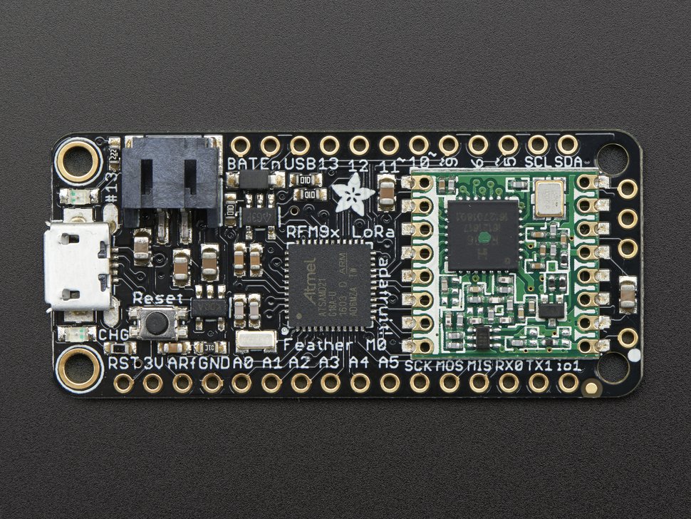
https://www.adafruit.com/product/3178
Il n'y a pas d'antenne intégrée. Il suffit d'un fil pour faire une "quarter wave whip antenna" en le coupant à la bonne longueur. Ici 8,2 cm.
LoRaWAN en C
On utilisera LMIC (LoRa Mac In C) et l'IDE Arduino. LMIC permet à un objet de se connecter à un réseau LoRaWAN. Se référer au link:../generic-lorawan-node-basic-join[tutoriel de connexion LoRaWAN] pour tous les détails sur l'utilisation de LMIC dans Arduino.
Ajout des pilotes
Il faut ajouter les pilotes pour les cartes de la famille SAMD dont fait partie le Feather.
Dans Fichier/préférences, ajouter comme gestionnaire de cartes additionnelles l'adresse : https://adafruit.github.io/arduino-board-index/package_adafruit_index.json
Puis, Outils/Type de Cartes/gestionnaire de cartes, recherchez Feather et installer les librairies (Adafruit SAMD Boards).
Plus d'infos ici : https://learn.adafruit.com/adafruit-feather-m0-radio-with-lora-radio-module/setup
Câblage
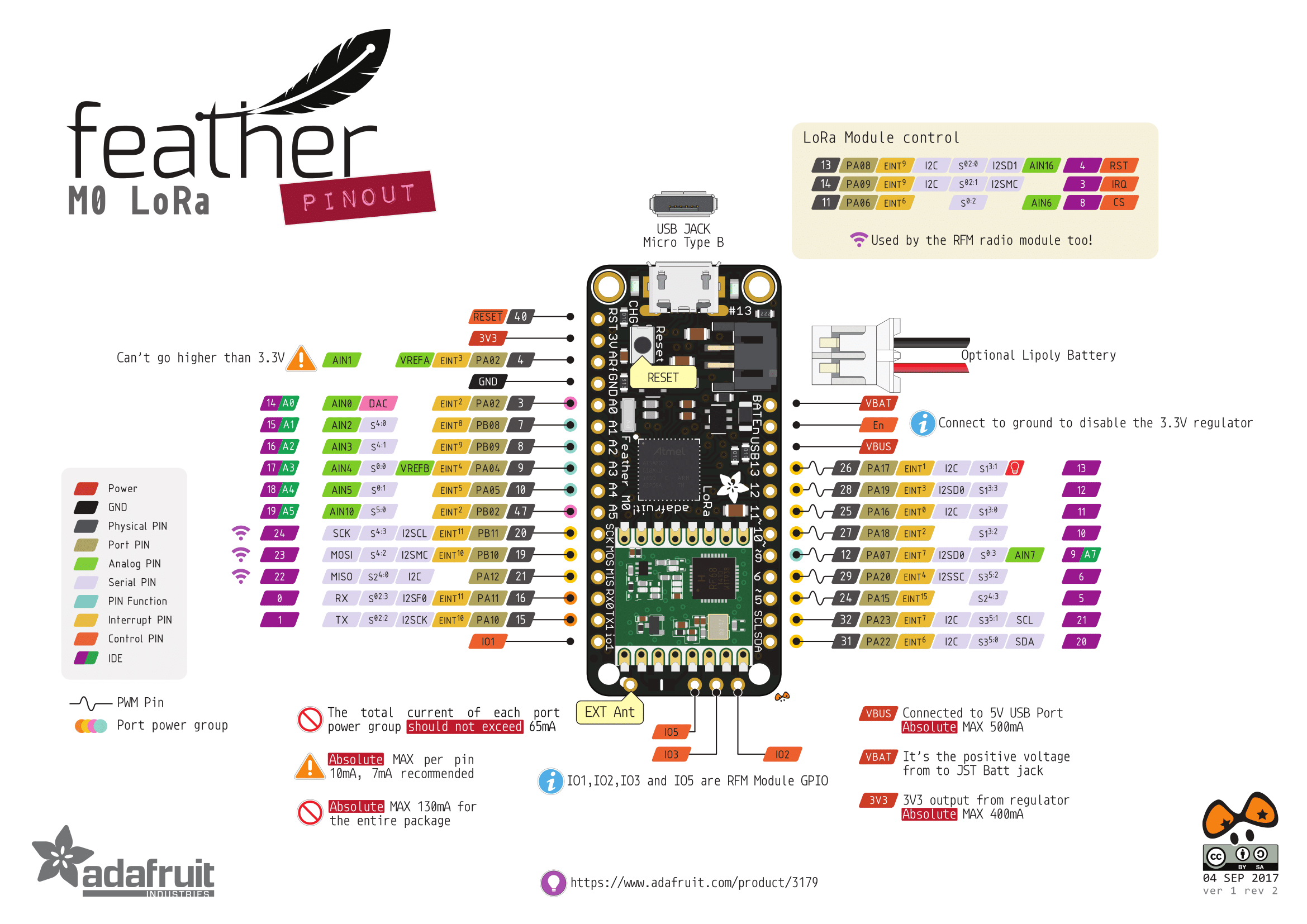
Comme d'habitude, on ajuste ici pinmap pour indiquer à LMIC quelles sont les GPIO à utiliser pour se connecter à la radio LoRa.
Le paramétrage pinmap du Feather M0 pour la pile LMIC est le suivant :
const lmic_pinmap lmic_pins = {
    .nss = 8,
    .rxtx = LMIC_UNUSED_PIN,
    .rst = LMIC_UNUSED_PIN,
    .dio = {3, 6, LMIC_UNUSED_PIN},
};
Comme la plupart des pins sont déjà connectés entre eux sur la carte. Il nous reste à connecter le pin 6 de la feather à IO1 :
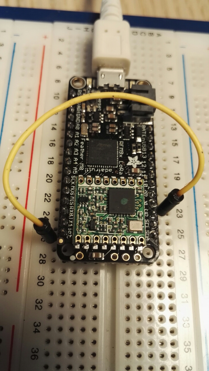
https://wolfgangklenk.wordpress.com/2017/04/15/adafruit-feather-as-lorawan-node/
=== Sketch d'exemple
/*******************************************************************************
 * Copyright (c) 2015 Thomas Telkamp and Matthijs Kooijman
 * https://github.com/matthijskooijman/arduino-lmic/blob/master/examples/ttn-otaa/ttn-otaa.ino
 * Modifié par NG et RB (IUT de Blagnac)
 *
 * This uses OTAA (Over-the-air activation), where where a DevEUI and
 * application key is configured, which are used in an over-the-air
 * activation procedure where a DevAddr and session keys are
 * assigned/generated for use with all further communication.
 *
 * To use this sketch, first register your application and device with
 * the tloraserver, to set or generate an AppEUI, DevEUI and AppKey.
 * Multiple devices can use the same AppEUI, but each device has its own
 * DevEUI and AppKey.
 *
 * Do not forget to define the radio type correctly in config.h.
 *
 *******************************************************************************/

#include <lmic.h>
#include <hal/hal.h>
#include <SPI.h>

/******************************************************************************/
/* LoRaWAN                                                                    */
/******************************************************************************/

// This EUI must be in *little-endian format* (least-significant-byte first)
// Necessaire pour le protocole mais inutile pour l'implémentation dans loraserver
// On peut donc mettre de l'aléatoire ou :

static const u1_t APPEUI[8]={ 0xF5, 0xD4, 0x54, 0x4B, 0x1C, 0xAB, 0x54, 0x1C };

// DEVEUI should also be in *LITTLE endian format*

//1a81070000000201 soit le YahIUT0201

static const u1_t DEVEUI[8]={ 0x01, 0x02, 0x00, 0x00, 0x00, 0x07, 0x81, 0x1a };

// This key should be in BIG endian format
// 00 00 00 00 00 00 00 00 1a 81 07 00 00 00 02 00

static const u1_t APPKEY[16] = { 0x00, 0x00, 0x00, 0x00, 0x00, 0x00, 0x00, 0x00, 0x1a, 0x81, 0x07, 0x00, 0x00, 0x00, 0x02, 0x00 };

// Copie en mémoire des EUI et APPKEY
void os_getArtEui (u1_t* buf) { memcpy_P(buf, APPEUI, 8);}
void os_getDevEui (u1_t* buf) { memcpy_P(buf, DEVEUI, 8);}
void os_getDevKey (u1_t* buf) { memcpy_P(buf, APPKEY, 16);}

// Schedule TX every this many seconds (might become longer due to duty
// cycle limitations).
const unsigned TX_INTERVAL = 60;

/******************************************************************************/
/* pin mapping                                                                */
/******************************************************************************/

const lmic_pinmap lmic_pins = {
    .nss = 8,
    .rxtx = LMIC_UNUSED_PIN,
    .rst = LMIC_UNUSED_PIN,
    .dio = {3, 6, LMIC_UNUSED_PIN},//io1 pin is connected to pin 6, io2 vers pin 11
};

/******************************************************************************/
/* payload                                                                    */
/******************************************************************************/

static uint8_t mydata[] = "RB";

/******************************************************************************/
/* Automate LMIC                                                              */
/******************************************************************************/

// return the current session keys returned from join.
void LMIC_getSessionKeys (u4_t *netid, devaddr_t *devaddr, xref2u1_t nwkKey, xref2u1_t artKey) {
    *netid = LMIC.netid;
    *devaddr = LMIC.devaddr;
    memcpy(artKey, LMIC.artKey, sizeof(LMIC.artKey));
    memcpy(nwkKey, LMIC.nwkKey, sizeof(LMIC.nwkKey));
}
static osjob_t sendjob;

void onEvent (ev_t ev) {
    Serial.print(os_getTime());
    Serial.print(": ");
    switch(ev) {
        case EV_SCAN_TIMEOUT:
            Serial.println(F("EV_SCAN_TIMEOUT"));
            break;
        case EV_BEACON_FOUND:
            Serial.println(F("EV_BEACON_FOUND"));
            break;
        case EV_BEACON_MISSED:
            Serial.println(F("EV_BEACON_MISSED"));
            break;
        case EV_BEACON_TRACKED:
            Serial.println(F("EV_BEACON_TRACKED"));
            break;
        case EV_JOINING:
            Serial.println(F("EV_JOINING"));
            break;
        case EV_JOINED:
            Serial.println(F("EV_JOINED"));
            {
              u4_t netid = 0;
              devaddr_t devaddr = 0;
              u1_t nwkKey[16];
              u1_t artKey[16];
              LMIC_getSessionKeys(&netid, &devaddr, nwkKey, artKey);
              Serial.print("netid: ");
              Serial.println(netid, DEC);
              Serial.print("devaddr: ");
              Serial.println(devaddr, HEX);
              Serial.print("artKey: ");
              for (int i=0; i<sizeof(artKey); ++i) {
                if (i != 0)
                  Serial.print("-");
                Serial.print(artKey[i], HEX);
              }
              Serial.println("");
              Serial.print("nwkKey: ");
              for (int i=0; i<sizeof(nwkKey); ++i) {
                      if (i != 0)
                              Serial.print("-");
                      Serial.print(nwkKey[i], HEX);
              }
              Serial.println("");
}

            // Disable link check validation (automatically enabled
            // during join, but not supported by TTN at this time).
            LMIC_setLinkCheckMode(0);
            break;
        case EV_RFU1:
            Serial.println(F("EV_RFU1"));
            break;
        case EV_JOIN_FAILED:
            Serial.println(F("EV_JOIN_FAILED"));
            break;
        case EV_REJOIN_FAILED:
            Serial.println(F("EV_REJOIN_FAILED"));
            break;
            break;
        case EV_TXCOMPLETE:
            Serial.println(F("EV_TXCOMPLETE (includes waiting for RX windows)"));
            if (LMIC.txrxFlags & TXRX_ACK)
              Serial.println(F("Received ack"));
            if (LMIC.dataLen) {
              Serial.println(F("Received "));
              Serial.println(LMIC.dataLen);
              Serial.println(F(" bytes of payload"));
            }
            // Schedule next transmission
            os_setTimedCallback(&sendjob, os_getTime()+sec2osticks(TX_INTERVAL), do_send);
            break;
        case EV_LOST_TSYNC:
            Serial.println(F("EV_LOST_TSYNC"));
            break;
        case EV_RESET:
            Serial.println(F("EV_RESET"));
            break;
        case EV_RXCOMPLETE:
            // data received in ping slot
            Serial.println(F("EV_RXCOMPLETE"));
            break;
        case EV_LINK_DEAD:
            Serial.println(F("EV_LINK_DEAD"));
            break;
        case EV_LINK_ALIVE:
            Serial.println(F("EV_LINK_ALIVE"));
            break;
         default:
            Serial.println(F("Unknown event"));
            break;
    }
}

// send fonction

void do_send(osjob_t* j){
    // Check if there is not a current TX/RX job running
    if (LMIC.opmode & OP_TXRXPEND) {
        Serial.println(F("OP_TXRXPEND, not sending"));
    } else {
        // Prepare upstream data transmission at the next possible time.
        LMIC_setTxData2(1, mydata, sizeof(mydata)-1, 0);
        Serial.println(F("Packet queued"));
    }
    // Next TX is scheduled after TX_COMPLETE event.
}

void setup() {
    Serial.begin(9600);
    while (millis() < 5000) {
    Serial.print("millis() = "); Serial.println(millis());
    delay(500);
  }
    Serial.println(F("Starting"));

    #ifdef VCC_ENABLE
    // For Pinoccio Scout boards
    pinMode(VCC_ENABLE, OUTPUT);
    digitalWrite(VCC_ENABLE, HIGH);
    delay(1000);
    #endif

    // LMIC init
    os_init();
    // Reset the MAC state. Session and pending data transfers will be discarded.
    LMIC_reset();
    LMIC_setClockError(MAX_CLOCK_ERROR * 10 / 100);
    // Start job (sending automatically starts OTAA too)
    do_send(&sendjob);
}

void loop() {
    os_runloop_once();
}
LoRaWAN en python
MicroPython est une implémentation du langage de programmation libre, sous licence MIT, Python, adapté au monde des microcontrôleurs.
CircuitPython est un fork de MicroPython, qui a pour objectif de créer une API plus simple et plus uniforme tout en l'adaptant aux matériels dévloppé par Adafruit.
Warning
Il y a un certain nombre de limitations pour LoRaWAN avec CircuitPython. Dans nos cas d'usage, rien de bloquant. Pour information, voir : https://learn.adafruit.com/adafruit-feather-m0-radio-with-lora-radio-module/circuitpython-for-rfm9x-lora
Installation de CircuitPython
Télécharger la dernière version de CircuitPython pour le Feather M0 RFM9x :
https://circuitpython.org/board/feather_m0_rfm9x/
On y télécharge le fichier d'extension ".UF2"
Tip
Une autre méthode consiste en télécharger le fichier ".bin" et flasher la carte avec le logiciel bossac
UF2 signifie "USB Flasher version 2".
Appuyer deux fois (comme un double clic) sur le bouton reset de la carte. Un nouveau lecteur devrait apparaître avec le nom FEATHERBOOT. La carte est en mode bootloader.
Il suffit pour terminer de copier/coller le fichier *.UF2 dans ce lecteur.
L'installation se lance automatiquement puis un lecteur nommé circuitpy apparaît :
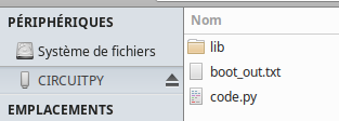
On peut tester l'installation avec le traditionnel blink. Dans le fichier code.py saisir :
import digitalio
import board
import time

led = digitalio.DigitalInOut(board.D13)
led.direction = digitalio.Direction.OUTPUT
while True:
    led.value = not led.value
    time.sleep(0.5)
Une fois sauvegardé, le code est éxécuté au bout de quelques secondes.
Ajout des bibliothèques
Pour ajouter des bibliothèques en plus, il suffit de les copier/coller dans le répertoire lib (le créer si nécessaire, attention à la casse).
De façon générale, on peut trouver des bibliothèques CircuitPython sur le GitHub d'Adafruit et via les tutoriels CircuitPython sur le Learning System d'Adafruit .
Le Feather M0 RFM9x a moins d'espace disponible que les autres cartes d'Adafruit. Nous allons donc ajoter que le strict nécessaire.
À partir du répertoire contenant toutes les librairies disponibles, choisir seulement les répertoires :
adafruit_bus_deviceadafruit_tinylora- et le fichier
adafruit_si7021
Choisir les fichiers "*.mpy" car ils sont compressés et les copier/coller dans le répertoire lib.
Pour gagner un peu d'espace, supprimer les fichiers ttn_as.mpy, ttn_au.mpy, ttn_as.mpy et ttn_usa.mpy. Supprimer également la corbeille du lecteur (Maj+Suppr).
Création du device dans loraserver
L'authentification ne peut se faire qu'en ABP pour le moment.
Vérifier sur loraserver que vous avez bien un device-profile avec OTAA désactivé.
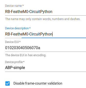
Choisir une application et y crééer le device comme d'habitude en séelctionnant le bon device-profile.
Ici, nous l'avons mis dans l'application 5 avec l'identifiant 010203040506070a
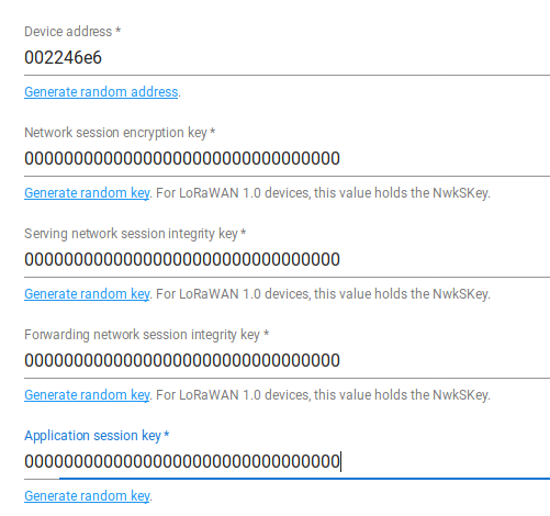
Les clés sont celles par défaut (à changer)
Network key : 00000000000000000000000000000000
Application key : 00000000000000000000000000000000
Il est conseillé de cocher la case Disable frame-counter validation (moins de sécurité...)
On pourra aussi générer des valeurs aléatoires au lieu de faire comme suit :
Code exemple
Toujours dans le https://github.com/adafruit/Adafruit_CircuitPython_Bundle/releases/latest[répertoire contenant toutes les librairies], on trouve un fichier zip contenant des exemples et notamment le fichier tinylora_simpletest.py :
import time
import busio
import digitalio
import board
from adafruit_tinylora.adafruit_tinylora import TTN, TinyLoRa

# Board LED
led = digitalio.DigitalInOut(board.D13)
led.direction = digitalio.Direction.OUTPUT

spi = busio.SPI(board.SCK, MOSI=board.MOSI, MISO=board.MISO)

# FeathM0 RFM9xPinout
cs = digitalio.DigitalInOut(board.RFM9X_CS)
irq = digitalio.DigitalInOut(board.RFM9X_D0)

# TTN Device Address, 4 Bytes, MSB
devaddr = bytearray([0x00, 0x22, 0x46, 0xe6])

# TTN Network Key, 16 Bytes, MSB
nwkey = bytearray([0x00, 0x00, 0x00, 0x00, 0x00, 0x00, 0x00, 0x00,
                   0x00, 0x00, 0x00, 0x00, 0x00, 0x00, 0x00, 0x00])

# TTN Application Key, 16 Bytess, MSB
app = bytearray([0x00, 0x00, 0x00, 0x00, 0x00, 0x00, 0x00, 0x00,
                 0x00, 0x00, 0x00, 0x00, 0x00, 0x00, 0x00, 0x00])

ttn_config = TTN(devaddr, nwkey, app, country='EU')

lora = TinyLoRa(spi, cs, irq, ttn_config)

data = bytes("Feather python RB", 'utf-8')

while True:
    #data = bytearray(b"\x43\x57\x54\x46")
    print('Sending packet..')
    lora.send_data(data, len(data), lora.frame_counter)
    print('Packet sent!')
    led.value = True
    lora.frame_counter += 1
    time.sleep(1)
    led.value = False
Console série
CircuitPython envoie la sortie d'un fichier .py en cours d'exécution vers la connexion USB-série.
Via n'importe quelle console, on peut donc voir les affichages et messages du programme. Par exemple :
picocom -b 115200 /dev/ttyACM0
ou :
screen /dev/ttyACM0 115200
Avec ce dernier Ctrl+C va permettre de passer en mode REPL (Read-Evaluate-Print-Loop). On se retrouve ainsi avec une console python avec laquelle intéragir.
MQTT
On peut récupérer les données en MQTT :
mosquitto_sub -h loraserver.tetaneutral.net -v -t "application/5/device/010203040506070a/rx"
Références
https://learn.adafruit.com/welcome-to-circuitpython/the-repl
https://wolfgangklenk.wordpress.com/2017/04/15/adafruit-feather-as-lorawan-node/